Kia Niro: Keyless Entry And Burglar Alarm / Repair procedures
| Inspection |
|
Front Door Lock Module Inspection
| 1. |
Remove the front door trim. (Refer to Body - "Front Door Trim") |
| 2. |
Remove the front door module. (Refer to Body - "Front Door Module") |
| 3. |
Disconnect the connector from the actuator.
[Central Lock Motor]
[Dead Lock Motor]
|
||||||||||||||||||||||||||||||||||||||||||||||||||||||||||
| 4. |
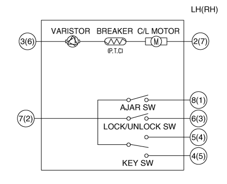
Check actuator operation by connecting power and ground as shown below. To prevent damage to the actuator, apply battery voltage only momentarily. [Central Lock Motor]
[Dead Lock Motor]
[Central Lock Motor] (LH)
(RH)
[Dead Lock Motor]
|
Rear Door Lock Module Inspection
| 1. |
Remove the rear door trim. (Refer to Body - "Rear Door Trim") |
| 2. |
Remove the rear door module. (Refer to Body - "Rear Door Module") |
| 3. |
Disconnect the connector from the actuator.
[Central Lock Motor]
[Dead Lock Motor]
|
||||||||||||||||||||||||||||||||||||||||||||||||||||||||||
| 4. |
Check actuator operation by connecting power and ground as shown below. To prevent damage to the actuator, apply battery voltage only momentarily. [Central Lock Motor]
[Dead Lock Motor]
[Central Lock Motor] (LH)
(RH)
[Dead Lock Motor]
|
Tailgate Lock Module Inspection
| 1. |
Remove the tailgate trim. (Refer to Body - "Tailgate Trim") |
| 2. |
Disconnect the connectors from the actuator.
|
| 3. |
Check actuator operation by connecting power and ground as shown below. To prevent damage to the actuator, apply battery voltage only momentarily.
|
| 4. |
Checking the tailgate of the vehicle power option power refers to the tailgate module. |
Tailgate Open Switch Inspection
| 1. |
Disconnect the negative (-) battery terminals. |
| 2. |
Remove the tailgate trim (Refer to Body - "Tailgate Trim") |
| 3. |
Remove the tailgate latch. (Refer to Body - "Tailgate Latch") |
| 4. |
Disconnect the tailgate open switch assembly connector.
|
| 5. |
Check for continuity between terminals in half latching condition as shown below.
|
Hood Switch Inspection
| 1. |
Disconnect the hood switch connector (A).
|
| 2. |
Check for continuity between the terminals and ground as shown below. (Refer to Body - "Hood Latch Assembly")
|
Burglar Horn Inspection
| 1. |
Remove the burglar horn (A) after loosening the mounting bolt and disconnecting the connector (B).
|
| 2. |
Test the burglar horn by connecting battery power to the terminal 2 and ground the terminal 1.
|
 Description and operation
Description
Burglar Alarm State
[B/A State]
B/A State
Description
DISARM
1)
This is the state when "AR ...
Other information:
Kia Niro 2017 (DE HEV) Service Manual: Schematic diagrams
Schematic Diagrams
Harness Connector
Item
Pin
Pin name
MDPS Power
1
Battery +
2
Battery -
MDPS Unit
1
Ignition
...
Kia Niro (DE HEV) Owners Manual: If An Accident Occurs
Avoid the engine compartment.
Avoid any orange or high voltage wires, cables, or components.
Assume that a high voltage component is exposed and move away from the vehicle
as promptly as possible.
Refer to Chapter 7 for towing information.
WARNING
After parking the vehicle, shift ...


